
iTriangle HW overview
Hardware Overview

| Part | Function |
|---|---|
| MCU | ESP8266 |
| Digital Port 0 | GPIO 14 |
| Digital Port 1 | GPIO 12 |
| Digital Port 2 | GPIO 13 |
| Analog Port | A3 |
| UART Port | Pin 1 & Pin 3 |
| I2C Port | Pin 4 & Pin 5 |
| Status Light | Blue LED is the WiFi status indicator, Red LED indicates the working status |
| Configure Button | To configure and manage your iTriangle |
| Battery Holder | JST2.0 |
| Micro USB | To power the board or communicate with a PC |
| Reset Button |
To reset the MCU |
| General | Value | Power Management | Value |
|---|---|---|---|
| Size | 55mm * 48mm | DC Current Per I/O Pin | 12 mA |
| Crystal | 26 MHz | Input Voltage (Micro USB) | 5 V |
| Flash Memory | 4 MBytes (W25Q32B) | Input Voltage (Battery holder) | 3.4~4.2 V |
| Wi-Fi Network Protocol | 802.11 b/g/n | Output DC Current | 1000 mA MAX |
| Wi-Fi Encryption Technology | WEP/TKIP/AES | Operating Voltage | 3.3 V |
| Grove Connectors | 6 | Charge Current | 500 mA MAX |
| Flash | 4 MB (W25Q32B) | LifeTime of FLASH | 10.000 write cycles |
Pay attention to FLASH write cycle limits. Programs are stored in FLASH and each new firmware build or offline code update increases the internal write count. After the FLASH write limit is exceeded, the board will probably work well for the next few thousands cycles, but there is no legal warranty for exceeding the limit.
Status LEDs
Two status LEDs, blue and red, can be seen near the FUNCTION button. The blue LED indicates network status and has the following blink patterns:
![]() blinking slowly – configuration mode
blinking slowly – configuration mode
![]() blinking twice quickly, then off for 1s – requesting IP address from router
blinking twice quickly, then off for 1s – requesting IP address from router
![]() blinking once quickly, then off for 1s – connecting to the server
blinking once quickly, then off for 1s – connecting to the server
![]() on for 1s, then off for 1s – the node is online
on for 1s, then off for 1s – the node is online
![]() continuously on – the node is not available/has no IP/not connected to server.
continuously on – the node is not available/has no IP/not connected to server.
![]() blinking quickly (on for 100ms, then off for 100ms) – OTA
blinking quickly (on for 100ms, then off for 100ms) – OTA
The blue LED is connected to GPIO2, which is also the TX pin of UART1. When downloading firmware, the UART1 dumps the data transmitting on UART0 automatically. The Bblue LED will therefore blink while downloading firmware. After startup, the GPIO2 will be configured as a GPIO, not TX of UART1.
The red LED is another status LED and indicates the power status of Grove modules. The six VCC headers converge and can be controlled with GPIO 15. When the node is in deep sleep mode, all of the modules lose their power too. The red LED will light up when the modules are powered and switch off when modules are not powered.
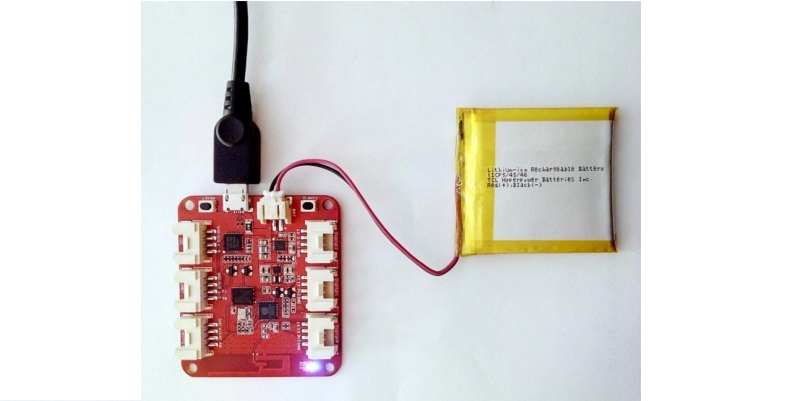
Bonus!
iTriangle has an inbuilt LiPo battery charger. You can charge a 3.7 V LiPo battery with the JST 2.0 Port when connected by USB.
Žádné komentáře